3 input nand gate circuit diagram Nand gate schematic diagram Logic nand gate working principle & circuit diagram
Nand Gate Layout
Logic circuits cmos nand integrated implementation lab4sys Introduction to logic gates [diagram] circuit diagram using nand gate
Nand gate logic transistors transistor bjt using circuit circuits input truth table schematic does work electrical inputs series tutorial digital
My 2nd try finding the easiest way to compare two 8-bit buses. can youCompuerta nand con un pmos y un nmos Logic nand gate tutorial with nand gate truth tableIn a 2-input nand, which will be faster when switching: when the a.
Nand gate transistor logicNand gate circuit diagram and working explanation Logic nand gate working principle & circuit diagramNand cmos pmos nmos circuit logic input transistors nor logica transistor electronics implementation porta switching nedir delay insensitive quasi gatter.
![Logic NAND Gate Tutorial with NAND Gate Truth Table](https://i2.wp.com/www.electronics-tutorials.ws/wp-content/uploads/2018/05/logic-log45.gif)
Nand gate schematic diagram iot wiring diagram images
[diagram] circuit diagram nand gateNand gate diagram Circuit diagram nand gate[diagram] circuit diagram nand gate.
And made of nands circuit diagramNand gate circuit diagram Nand gate layoutC-mos logic integrated circuits.
![My 2nd try finding the easiest way to compare two 8-bit buses. Can you](https://i2.wp.com/allabouteng.com/wp-content/uploads/2018/05/NMOS-NAND-Gate-Schematic.jpg)
Nand gate internal diagram
Cmos nand gate circuit diagramElectronic – multi-level nand circuit simple conversion – valuable tech .
.
![Nand Gate Circuit Diagram And Working Explanation - Photos](https://i2.wp.com/www.vedantu.com/question-sets/f6b02a33-7b4a-4281-974e-46e122ffeb874155025550617684001.png)
![Logic NAND Gate Working Principle & Circuit Diagram](https://i2.wp.com/www.electroniclinic.com/wp-content/uploads/2022/08/a.-NAND-gate-logic-symbol-b.-A-Boolean-expression-for-the-output-of-a-NAND-gate-c.-Truth-table-for-AND-NAND-gate-681x720.jpg)
Logic NAND Gate Working Principle & Circuit Diagram
![Nand Gate Diagram](https://i2.wp.com/www.engineersgarage.com/wp-content/uploads/2019/07/Circuit-Diagram-For-Conversion-of-NAND-gate-to-Basic-gates.gif)
Nand Gate Diagram
![3 Input Nand Gate Circuit Diagram](https://i2.wp.com/i.stack.imgur.com/Nh942.png)
3 Input Nand Gate Circuit Diagram
In a 2-input NAND, which will be faster when switching: when the A
![Nand Gate Schematic Diagram - Wiring Diagram](https://i2.wp.com/www.vedantu.com/question-sets/f6b02a33-7b4a-4281-974e-46e122ffeb874155025550617684001.png?strip=all)
Nand Gate Schematic Diagram - Wiring Diagram
![Nand Gate Transistor Logic | Free Nude Porn Photos](https://i2.wp.com/www.petervis.com/Education/logic-gates/nand-gate-transistor-circuit/nand-gate-transistor-circuit.gif)
Nand Gate Transistor Logic | Free Nude Porn Photos
![compuerta NAND con un pMOS y un nMOS - Electronica](https://i2.wp.com/i.stack.imgur.com/vioxn.png)
compuerta NAND con un pMOS y un nMOS - Electronica
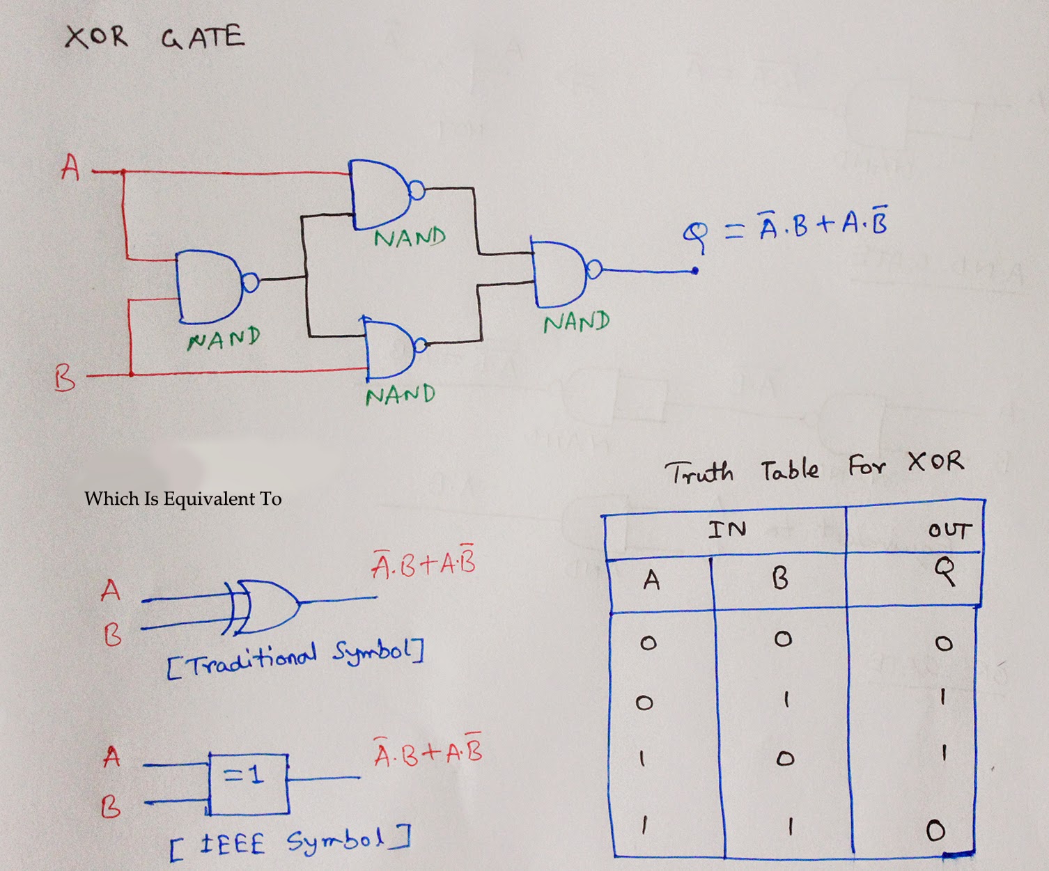
![And Made Of Nands Circuit Diagram](https://2.bp.blogspot.com/-4RfqzLgPqdE/U4mrdCDNgDI/AAAAAAAABQQ/R8-_f_kDEm8/s1600/XOR+using+NAND.jpg)
And Made Of Nands Circuit Diagram
![Nand Gate Layout](https://i2.wp.com/www.researchgate.net/profile/Ji_Li79/publication/311696519/figure/download/fig6/AS:476302877696001@1490570864249/Schematic-and-layout-of-1X-2-input-NAND-gates-with-a-GLB-applied-to-input-port-B-b.png)
Nand Gate Layout